Clarifying architecture with Service Blueprints: system operations
service blueprint architecture architecting assemblageContact me for information about consulting and training at your company.
The MEAP for Microservices Patterns 2nd edition is now available
I’ve previously written about how Service Blueprints are a really useful tool for documenting and understanding the architecture of a system. A service blueprint is a diagram that shows the interactions between the user, and the architectural elements. Along the top of the blueprint are the steps of the user journey. Underneath each step are the architectural elements that enable that step.
Architecture is, as I’ve previously written, multi-dimensional. Each dimension has different types of architectural elements. In this post I’ll describe how service blueprints can be used to document the system operations that are discovered in step 1 of the Assemblage process.
Discovering systems operations
Step 1 of the Assemblage architecture definition process distills the application’s requirements into a set of system operations.
A system operation is an externally invokable behavior implemented by the application.
It reads and/or writes one or more business entities, a.k.a. DDD aggregates, such as Customer and Order.
A system operation has a parameters, and an operational return value and can be thought of as a method implemented by the application.
Collectively, the system operations model the application’s black box behavior.
System operations are often invoked by the user
System operations are invoked in one of three ways: human users, other applications, and the passing of time. In many applications, the user is the primary actor. As a result, service blueprints are often a useful part of the documentation for system operations. Let’s look at an example.
A service blueprint for placing an order
The Place Order scenario consists of the following user actions:
- Enter delivery address and desired delivery time
- Select an available restaurant
- View the shopping cart
- Pay
The following diagram shows the service blueprint for this scenario.
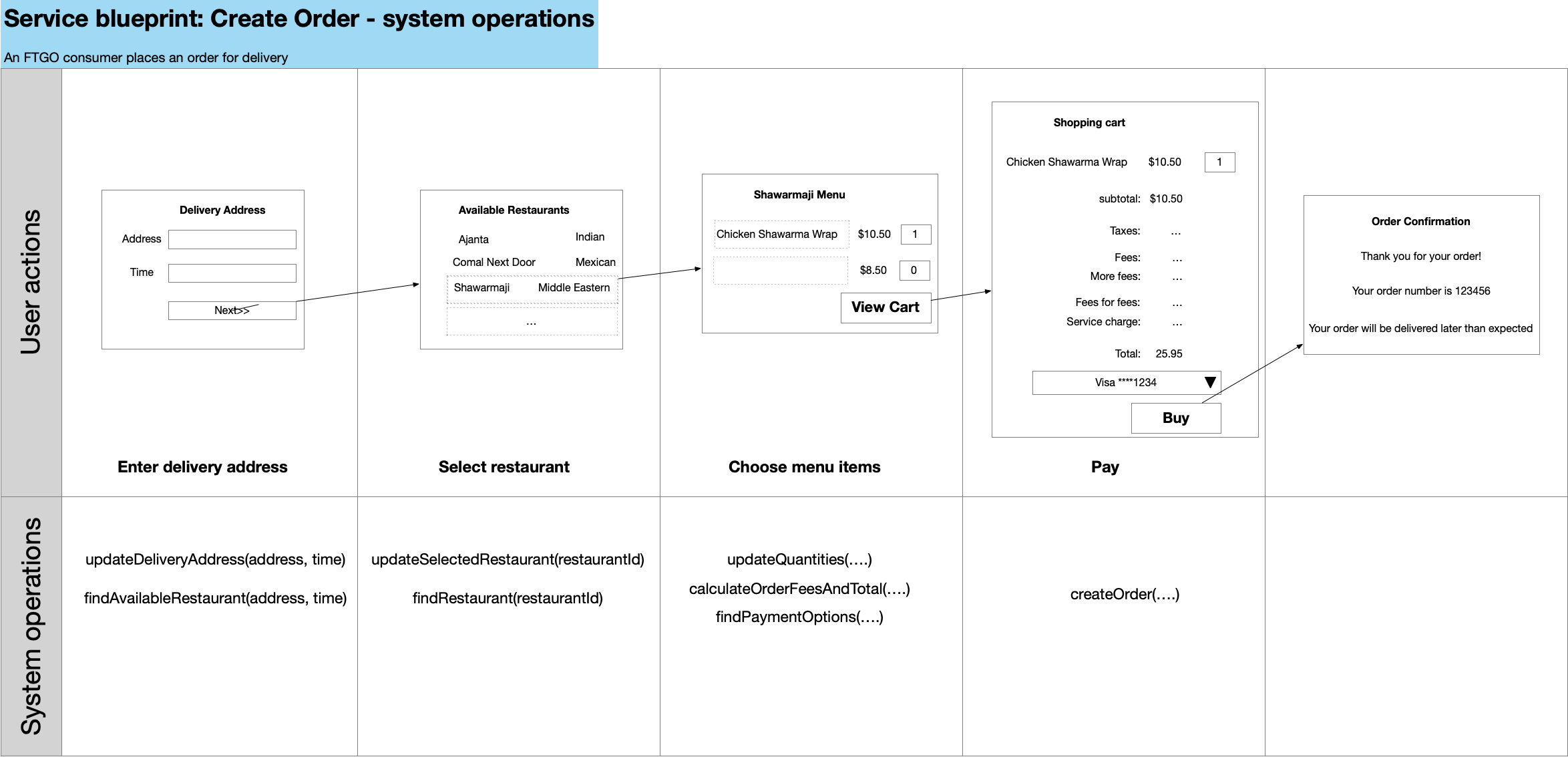
Along the top of the blueprint are the user actions and along with a wireflow mockup of the page that the user sees.
Underneath each user action are the system operations that are invoked in response to the user action.
System commands update business entities and system queries retrieve business entities in order to populate the next page.
For example, when the user enters the delivery address and desired delivery time, the findAvailableRestaurants() system query is invoked.
The results of this query are used to populate the next page, which displays the list of available restaurants.
When the user, clicks the ‘Buy’ button, the createOrder() system command is invoked, which creates the Order.
The blueprint connects system operations to user actions
What’s particularly useful about this blueprint is that it connects the system operations to the user actions. The intent of each system operation is clear from the user action that triggers it and, in the case of query, the design of the next page.
What’s next
In the next article, I’ll describe a more elaborate version of this service blueprint that includes additional useful information.
Need help with modernizing your architecture?
I help organizations modernize safely and avoid creating a modern legacy system — a new architecture with the same old problems. If you’re planning or struggling with a modernization effort, I can help.
Learn more about my modernization and architecture advisory work →

 Premium content now available for paid subscribers at